AIOGF‑SD‑8.4.1 — Workflow Control Mechanisms
This supplement defines the workflow‑level control mechanisms that ensure safe, predictable, and governable AI system behavior.
Diagram 1: Recursion Detection Call‑Graph
This diagram illustrates how the system detects and blocks both direct and indirect recursion across AI workflows.

Detailed Description:
This diagram shows how the system identifies and prevents recursion within AI workflows. It includes both direct recursion (a workflow calling itself) and indirect recursion (multiple workflows forming a loop such as A → B → C → A).
The Recursion Guard monitors the call‑graph in real time, detects cycles, terminates the workflow, and emits telemetry for audit and review.
Governance Interpretation:
Recursion is a high‑risk condition that can cause runaway execution, unbounded cost, and unpredictable behavior. This diagram demonstrates how the system enforces safety by blocking recursive call patterns.
Technical Interpretation:
The system maintains a depth‑aware call‑graph and evaluates each call against previously executed nodes. When a loop is detected, execution is halted and logged.
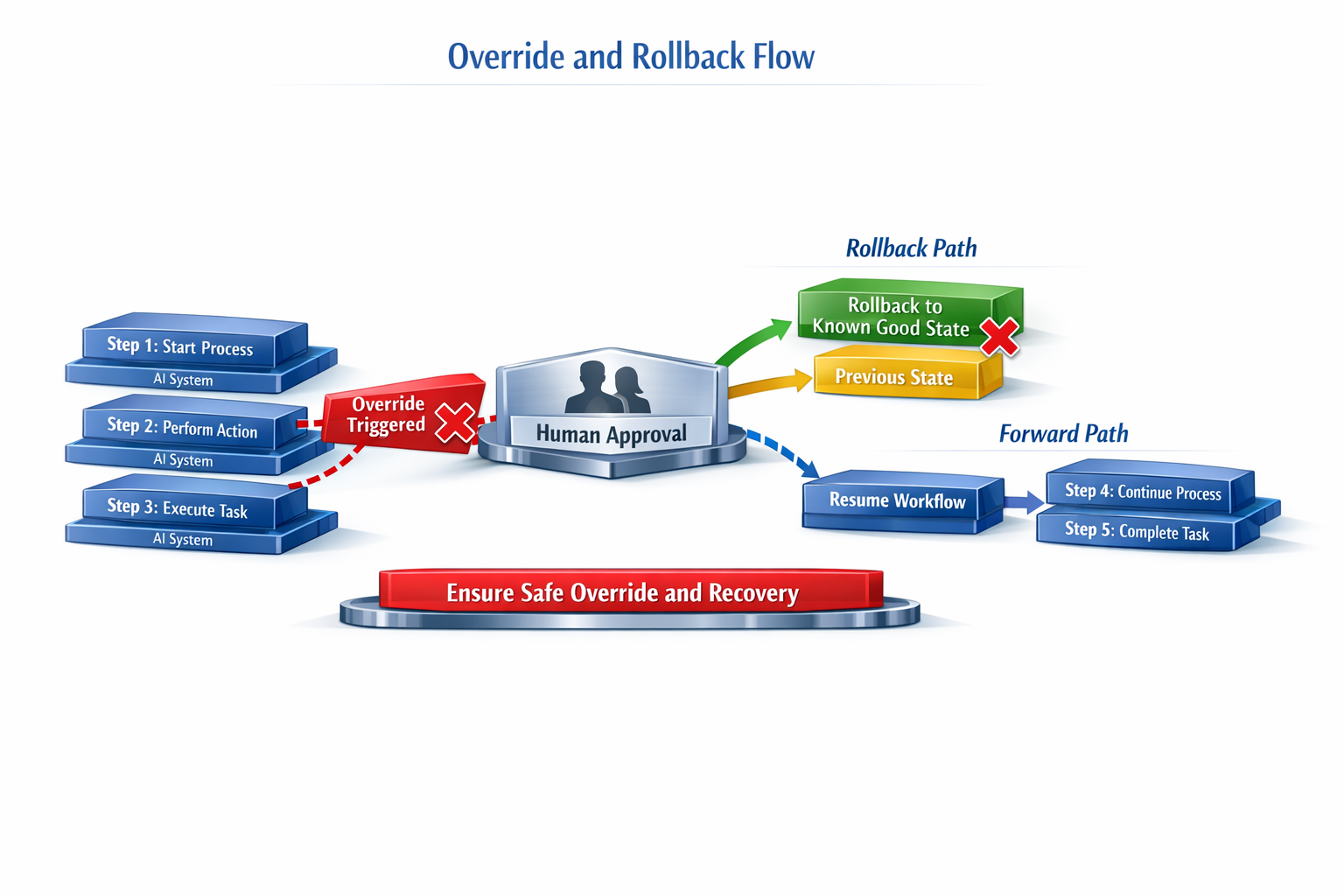
Diagram 2: Override and Rollback Flow
This diagram shows how an override interrupts workflow execution, routes control to a human approval node, and branches into rollback or resume paths.
Detailed Description:
The diagram depicts a linear workflow (Steps 1–5) with an override trigger that can occur at any point. When triggered, the workflow pauses and transitions to a Human Approval checkpoint.
From this checkpoint, two outcomes are possible:
- Resume Workflow: execution continues forward.
- Rollback to Known Good State: execution returns to a previously captured state snapshot.
Governance Interpretation:
Overrides ensure that humans retain authority over AI workflows during unexpected or high‑risk conditions. This mechanism prevents autonomous continuation when human judgment is required.
Technical Interpretation:
The system captures workflow state at each step, enabling deterministic rollback. Approval decisions and rollback actions are logged for auditability.
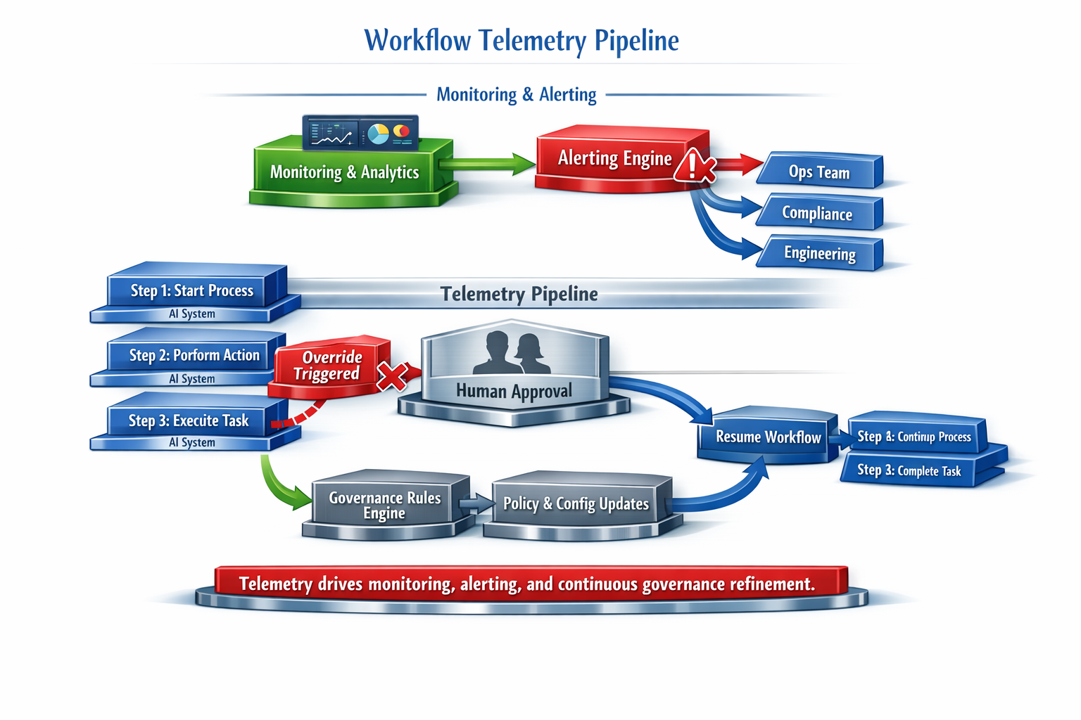
Diagram 3: Workflow Telemetry Pipeline
This diagram illustrates how telemetry flows from AI workflows into monitoring, alerting, and governance feedback.
Detailed Description:
The diagram shows how telemetry is emitted from each workflow step and flows into a centralized Telemetry Collector. The pipeline includes a Telemetry Processor for enrichment and filtering, a Telemetry Data Store for retention, and branches for monitoring, alerting, and governance analysis.
A governance feedback loop updates policies based on observed behavior.
Governance Interpretation:
Telemetry is the foundation of AI oversight. It enables visibility, accountability, anomaly detection, and continuous improvement of governance controls.
Technical Interpretation:
The pipeline supports real‑time monitoring, long‑term storage, anomaly detection, and automated policy refinement. Telemetry events are normalized and enriched for consistent analysis.
Diagram 4: Environment‑Specific Workflow Limits
This diagram shows how workflow depth limits differ across Development, Production, and Critical Operations environments.

Detailed Description:
The diagram compares workflow depth limits, checkpoint requirements, and autonomy levels across multiple environments. Each environment includes a workflow panel, a depth limit indicator, a gauge showing current depth, and a status indicator (Safe, Warning, Violated).
Development environments allow higher limits and flexibility; Production environments enforce strict limits; Critical Operations environments enforce the most restrictive boundaries.
Governance Interpretation:
Different environments have different risk profiles. Workflow limits must be tailored to each environment to ensure safety without restricting innovation.
Technical Interpretation:
Environment metadata is evaluated at runtime to enforce the correct depth, checkpoint, and telemetry rules. Violations generate alerts and telemetry events.
Diagram 5: Cross‑AI Interaction Map
This diagram visualizes allowed and blocked interactions between AI agents, including boundary enforcement points.

Detailed Description:
The diagram shows multiple AI systems (AI‑A, AI‑B, AI‑C) and the interactions between them. Allowed interactions are shown with solid lines; blocked or unauthorized interactions are shown with red or dashed lines.
A boundary represents the approved cross‑AI allow‑list, and enforcement points prevent unauthorized calls.
Governance Interpretation:
Cross‑AI interactions are a major source of risk. This diagram demonstrates how boundaries prevent privilege escalation, unintended chaining, and unauthorized access.
Technical Interpretation:
Each cross‑AI call is evaluated against an allow‑list. Unauthorized interactions are blocked and logged, ensuring strict control over multi‑agent workflows.
This document is part of the AI Operational Governance Framework (AI-OGF) and is protected under the AI-OGF Limited Use License. Official source: https://rmanthey-mantheyco.github.io/ai-ogf/